The way to steady pump operation
Centrifugal pumps to be used in the petrochemical industry must meet special standards of the American Petroleum Institute (API). For the requirements of API 610, the pump characteristic curve must be stable, among others. Particularly in the case of very small flow rates, care must be taken to avoid characteristic curve instabilities and to ensure that the head of the pump increases steadily - or at least does not decrease - as the flow rate decreases. Particularly in the case of semi-axial pumps with a downstream return section, the main focus must be on the blade-free space between the impeller and the diffuser, in which area rotating stall typically occurs that impairs both the pump head and the pump efficiency. Furthermore, API 610 also specifies the range of pressure pulsations in a wide variety of operating ranges that must be demonstrably complied with.

Diameter as a limiting factor
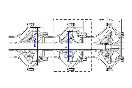
However, there are limits to the free design of the hydraulics in a vertical tubular casing pump. Above all, the diameter of the pump unit is a limiting factor. In order to reduce the number of pump stages arranged one after the other, the goal must simultaneously be to maximise the delivery head per stage. This in turn has a negative effect on the cavitation behaviour of the suction stage, which must never be neglected in hydraulic optimisation.
The approach to optimising the pump presented here is therefore a typical example of multi-objective optimisation. The aim is to find geometry parameters of the pump hydraulics that have a positive effect on the characteristic curve shape as well as on the efficiency, cavitation behaviour and vibration behaviour - with a minimum diameter and the shortest possible stage length.
Optimisation in various fields
The problem of multi-objective optimisation was addressed with a multidisciplinary optimisation approach. The maximum length per stage was set in advance by the client. With the help of various geometry recommendations, the meridian section of the pump impeller was first designed and the blading was designed one-dimensionally for this purpose. Using the Ansys-Bladegen software package, a 3D model of the hydraulics was created, meshed with hexahedral elements and the flow was simulated numerically in a stationary manner using Ansys-CFX. The calculation results were analysed and optimisation measures were derived from them in each case, with which the geometry parameters were changed "manually".


Based on the findings of the CFD simulation, the impeller of the pump was thus optimised step by step. For the return section or the diffuser of the pump, on the other hand, a fully parameterised 3D model was designed. Using the so-called design-of-experiment (DoE) and the response surface method, selected geometry parameters were automatically optimised. To obtain reliable calculation results for the highly transient flow in the partial load range, the performance of the entire pump stage was also validated using transient CFD simulations. The acceptance test by the user was finally carried out in the course of a model test in the laboratory; the homologous model machine was also built by our engineers. With the help of experimental investigations according to ISO9906 and various recordings with high-speed cameras, the 3D CFD simulation results were confirmed for the entire application range of the pump.
Special focus on part-load behaviour
Special attention was paid to the part-load behaviour of the pump in the course of the model test. Thus, the vibrations on the pump were measured in operation at various positions to provide evidence that the vibration velocities do not exceed the API 610 limit value of 5 mm/s. Furthermore, the full operating range up to zero head could be declared acceptable, as the increase in vibrations with respect to the machine's best efficiency point was always kept below 30 %. In addition, pressure pulsations were recorded, for example, in the bladeless space between the impeller and diffuser over the entire operating range of the pump. The frequency and amplitude of the measured pressure pulsations increase strongly towards partial load operation (Q/Qopt towards 0). This can be explained by the increasingly strong formation of the rotating detachments in the blade-free space and the development of a suction recirculation in the inlet area of the pump. The evaluation of the CFD simulations with regard to turbulence illustrates this thesis.
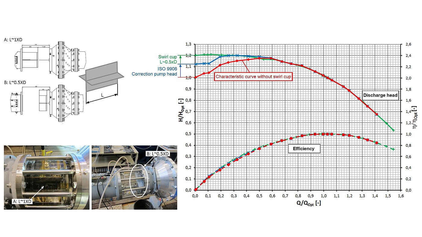
The start of pre-swirl with decreasing flow rate not only influences the pressure pulsations, but also causes the measured head to decrease significantly. This is the case because the centrifugal force of the suction recirculation causes an increase in the pressure on the suction side, which, however, does not originate from the inflow but from the pump itself. Consequently, ISO 9906 allows for a head correction. In the course of the test, it was shown that the drop in zero head can be completely prevented by installing a swirl breaker, which thus contributes to stabilising the pump characteristic curve.
Conclusion
The operator of the optimised pump therefore not only benefits from a highly efficient solution, but can also look forward to stable partial load operation of the pump and low noise and pulsation development. The reduction of pressure pulsations not only has a positive effect on the service life of the pump, but also on the quiet and low-maintenance operation of the entire system.
You might also be interested in this:
Canned Motor Pumps
Simulation and optimisation
Research on Process Pumps
Optimisation of side channel pumps
Stay up to date
Subscribe to our newsletter and stay up to date on our activities, continuing education and conferences.
We are your independent expert for:
- On-site measurements according to IEC 60041 and IEC 62006
- Acceptance tests and model tests according to IEC 60193, ISO 9906, IEC 60534, IEC 62006
- Plant, operation and life cycle tests
- Endurance test
- Comparison of experimental data with numerical simulation (3D-CFD)
- Analysis, design and optimisation of hydraulic machines, components and complete systems
- Water hammer and pressure surge as well as transient conditions of fluid and gas flows
- Fluid-structure interaction
We look forward to your enquiry!
Our experts for your fluid technology issues for pumps and systems:

Jürgen Schiffer-Rosenberger
Dipl.-Ing. Dr.techn.
CEO and and Managing Partner

Stefan Höller
Dipl.-Ing.
Chief Engineer

Christian Bodner
Dipl.-Ing.
Chief Engineer
