Achieving pump head curve stability
with CFD methods
In order to meet the requirements for a stable pump head curve, a low pump efficiency is often accepted. The example of a multistage borehole pump shows how this dogma can be broken by means of CFD methods.
The pump series in the presented example is used wherever liquid media have to be lifted from great depths. The areas of application range from energy supply, keyword geothermal energy, to chemical or industrial applications such as crude oil production, to water extraction from deep wells. The pump stages are modular, compact and simple in design and consist of the stage casing, which includes the bearings and the guide vanes, an impeller and a shaft.
The diffuser, in which part of the kinetic energy generated in the impeller is converted into static pressure, is a cast construction permanently integrated in the stage housing. The diffuser has the additional task of guiding the pumped liquid to the impeller inlet of the following stage with minimal losses and in a fluidically favourable manner. The closed impellers are hydraulically balanced via wear rings and balancing holes, which means that the remaining axial loads can be reduced to a minimum. By adjusting the number of stages - more than 40 stages are possible - the borehole pump is adapted to the required delivery head, in the application case more than 600 m, of the respective application. The submersible motor, in the application case with more than 1.5 MW power at a diameter of less than 190 mm and a length of about 25 m, is situated in the borehole under the suction piece of the pump and is cooled by the pumped medium.
Diagnosis: unstable characteristic curve
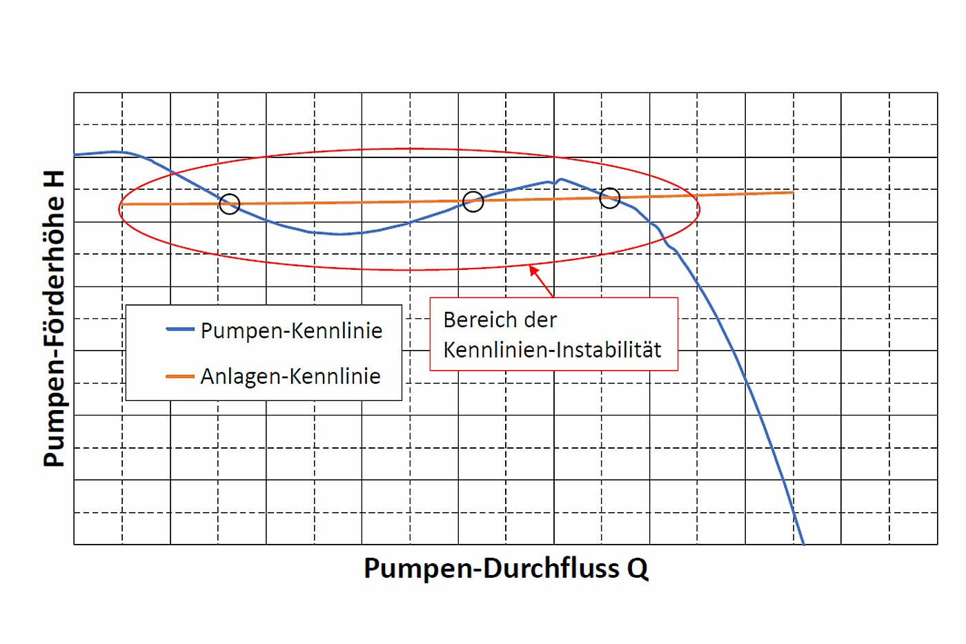
One problem with the pump under investigation was an unstable head curve. The diagram shows an example of the pump head curve of the investigated multistage borehole pump, which has a strongly pronounced head curve instability. The system resistance curve of the deep well pumping system is also shown. This system curve intersects the pump head curve in the area of the instability region. Hence, there are several intersections possible, marked with black circles, that lead to three possible operating points. Sudden jumps in the flow rate from one possible operating point to another can occur if the system resistance curve my change during operation.
This unstable range of the head curve is also passed through every time the pump is started and stopped - the result is abrupt changes in flow at every start and stop. If the flow changes rapidly, this leads to pressure surges that can damage the pump or other components of the relevant hydraulic system such as pipes, fittings and valves. Therefore, a stable pump curve is often mandatory, for example in the petrochemical industry - as stated in the API 610 standard.
Determine the cause with CFD
By means of numerical simulation (CFD), the existing pump was to be examined and possible causes for the unstable head curve identified and resolved. At the same time, it was necessary to analyse whether the efficiency could be improved. In the course of the optimisation, however, the main dimensions of the pump were not allowed to be changed. This ensures that in existing systems the pumps can be replaced 1:1 with the improved pump design.
To achieve the most accurate simulations possible, an extracted fluid volume with many details is necessary, which is then numerically meshed. The impeller and diffuser were rebuilt and meshed using reverse engineering. In this way, the blade surface of the impeller and the diffuser could be extracted and rebuilt in a CAD tool especially for turbomachinery in order to be able to modify the blade shape quickly and easily during the subsequent optimisation process.
Finally, a CFD model of the real pump was created that was as accurate as possible and the simulation results thus obtained could be compared with existing measurement results verified on the test rig. The comparison of simulation and measurement results ensures that the results and conclusion from the numerical simulation correspond to reality.
Identify and remedy weak points
The improvement of the actually multistage centrifugal pump was then mainly carried out in a simplified simulation model in order to minimise the computational effort. The impeller and its blade shape were improved manually, which requires corresponding expertise. By analysing the calculated flow field, weak points of the blade shape can be identified and ideally improved through geometry modifications. Iteratively, a blade shape adapted to the respective application is found.
Automated geometry optimisation, on the other hand, requires a fully parameterised CAD model of the selected components and sufficient computing capacity for the many simulation loops required. In the present application, such a parametric model with about 25 degrees of freedom was created for the diffuser. The solution was found in the course of a multi-objective optimisation based on evolutionary strategies. To reduce the computational effort, a mathematical meta-model of the optimisation objectives was created.
The following findings were obtained through extensive analyses:
- The stability of the pump characteristic depends essentially on a perfect interaction of impeller and diffuser. Both components must be matched to each other and should be optimised together. A short distance between the diffuser and the impeller of the following stage also has a positive effect on the head curve stability.
- The improved pump has seven impeller blades and eleven diffuser blades, as a result of the parametric optimisation model.
- The outer diameter of the stage has a major influence on the head and efficiency at all operating points investigated, and it can be seen that the larger the better. However, as for the borehole application it is not possible to increase the casing outer diameter.
- It should be taken into account in each iteration loop that the resulting blade shape is fabricable.
Result: Blade shape with stable head curve
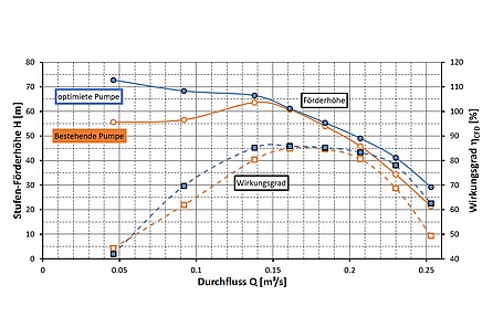
Through a hybrid approach of manual and automated optimisation, the impeller and diffuser could be successively improved. All design specifications were met during the process. In the course of the optimisation, a blade shape with a stable curve was found on the basis of the CFD simulations. This was achieved by minimising secondary flow influences such as flow separation and recirculation in partial load - as shown in the comparison of the flow field in the meridian section in partial load operation at 50% Qopt. At this operating point, the flow in the existing impeller design is already detached, whereas stall could be prevented by the new design. Finally, the pump improved by CFD simulations was validated by means of test rig measurements.
The described, simulation-supported optimisation approach will also allow other pumps in single- or multi-stage design to be improved in a similar way in the future. Based on the optimisation measures derived, it is not only possible to increase efficiency and reduce energy requirements - if required, the cavitation behaviour can also be improved and, in most cases, a more compact and thus more cost-effective pump design can be found.
You might also be interested in this:
The way to steady pump operation
Centrifugal pumps in the petrochemical industry must have a steady head curve acc. to API. How this can be improved and the efficiency optimised at the same time can be shown on the example of a vertical tubular casing pump.
Energy Efficient Pump Systems
Optimisation potentials throug speed control
Stay up to date
Subscribe to our newsletter and stay up to date on our activities, continuing education and conferences.
We are your independent expert for:
- On-site measurements according to IEC 60041 and IEC 62006
- Acceptance tests and model tests according to IEC 60193, ISO 9906, IEC 60534, IEC 62006
- Plant, operation and life cycle tests
- Endurance test
- Comparison of experimental data with numerical simulation (3D-CFD)
- Analysis, design and optimisation of hydraulic machines, components and complete systems
- Water hammer and pressure surge as well as transient conditions of fluid and gas flows
- Fluid-structure interaction
We look forward to your enquiry!
Our experts for your fluid technology issues for pumps and systems:

Helmut Jaberg
O.Univ.-Prof. em. Dipl.-Ing. Dr.techn.
CEO (Managing Partner)


