Best practice – field measurement
Acoustic flow measurements
One of the main challenges by conducting field measurements at powerplants is to determine the flowrate with high accuracy during simultaneous operation.
Acoustic flow measurement offers an optimal solution in many cases. For this purpose, clamp-on sensors are mounted to the outer wall of a steel pipe. The advantage - modifications to the pipeline do not have to be made and plant operation is not disturbed.
The Methodology
In a stationary fluid, the pressure changes of a acoustic signal propagate in all directions at the sound velocity a. In moving fluids, however, the relative velocity of sound changes with the fluid velocity. If the direction of flow w of the fluid in the direction of propagation shows sound waves, their velocities are superimposed to a + w. Contrary to the direction of flow, the resulting velocity is a - w. This means that an acoustic signal needs longer against the flow than with the flow to pass through a defined measuring distance. The resulting transit time difference is a measure of the average flow velocity wm, from which the flow Q can then be determined by the known area A.

However, since even small temperature fluctuations change the speed of sound a so considerably (∆a = 3.7m/s for water at ∆Θ= 1°C) that the change ∆a can be of the order of magnitude of the measured value wm and above, the two equations are subtracted to obtain a relationship independent of the speed of sound. This is achieved by measuring the transit times t1and t2 simultaneously. The method described is the most accurate for large pipe diameters; in experiments with internal sensors, accuracies of less than 5 per mil have already been demonstrated.
The on-site measurement
Between 1928 and 1930, this Romanian hydropower plant was built to supply Bucharest with electrical energy. The power station is equipped with four 2-jet Pelton turbines from Voith-Hydro and with Brown Boveri power station generators.


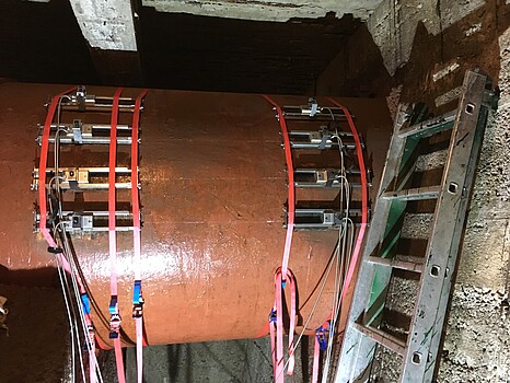
The turbine was measured with a Flexim ultrasonic flowmeter with 4 pairs of sensors which is the only mobile system with 4 measurement paths on the market and was specifically built for us.
To ensure high accuracy, the surface of the pipe was carefully cleaned at the beginning of the measurement and four independent pairs of sensors were installed in reflection mode. This mode provides 8 paths through the water and is a good compromise between high accuracy and signal rejection.


The discharge Q was determined by multiplying the cross-sectional area by the mean value of the flow velocity of each pair of sensors, that is calculated based on the transit time difference Δt between the two signals in both directions.
In addition to the flowrate, the excess pressure at the turbine inlet (related to the turbine reference level), nozzle position, the water temperature, the generator power output, the environmental data (ambient pressure, air temperature, air humidity,) were recorded.

Overall 9 different operation points were measured. During the measurements, the turbine operation points were partially unstable because of power grid fluctuations. As a result of the unstable power grid, the turbine control system was permanently readjusting the nozzle position. Out of this reason and for validating the measurements, 3 operation points were set again and measured a second time.
You might also be interested in this:
Best Practice - Field Measurement
Flow rate measurement according to IEC by means of impeller anemometer
Plant Measurement acc. to IEC
Our measuring methods
Stay up to date
Subscribe to our newsletter and stay up to date on our activities, continuing education and conferences.
We are your independent expert for:
- On-site measurements according to IEC 60041 and IEC 62006
- Acceptance tests and model tests according to IEC 60193, ISO 9906, IEC 60534, IEC 62006
- Plant, operation and life cycle tests
- Endurance test
- Comparison of experimental data with numerical simulation (3D-CFD)
- Analysis, design and optimisation of hydraulic machines, components and complete systems
- Water hammer and pressure surge as well as transient conditions of fluid and gas flows
- Fluid-structure interaction
We look forward to your enquiry!
Our experts for on-site measurement acc. to IEC:

Jürgen Schiffer-Rosenberger
Dipl.-Ing. Dr.techn.
CEO and and Managing Partner

Stefan Höller
Dipl.-Ing.
Chief Engineer

Christian Bodner
Dipl.-Ing.
Chief Engineer


