

As part of an extensive power plant modernisation project, we were commissioned some time ago to develop and optimise a new Kaplan runner for a hydroelectric power plant in Angola. The power plant, which went into operation in 1959, is equipped with three Kaplan turbines. The nominal data of the power plant are summarised as follows:


CFD techniques were used to simulate the hydraulic behaviour, which corresponds to the specifications of the new recommended hydraulic geometry and turbine speed for the existing hydropower plant.
The numerical simulation by CFD is based on experience gained from real model tests in accordance with IEC 60193. The advantage of this calculation method lies in its speed, ease of adaptation and the possibility of testing the prototype in its original size without having to apply efficiency transformations due to model/prototype scaling.
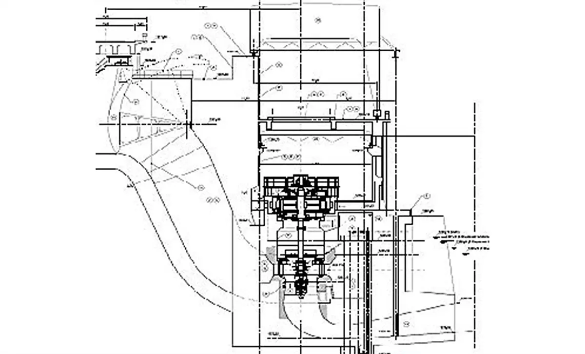
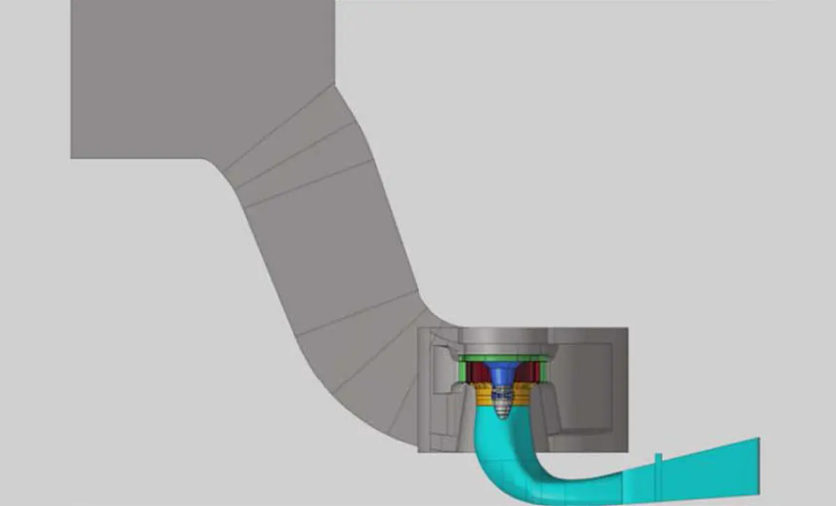
In the first step, the entire system, including the geometry of the spiral, the guide vanes, the runner shroud and the draft tube (consisting of the draft tube cone, elbow and horizontal diffuser), was reproduced in a 3D model based on the existing geometries.
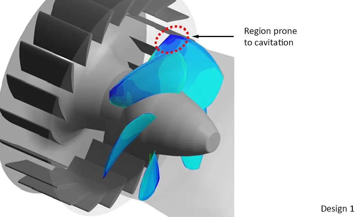
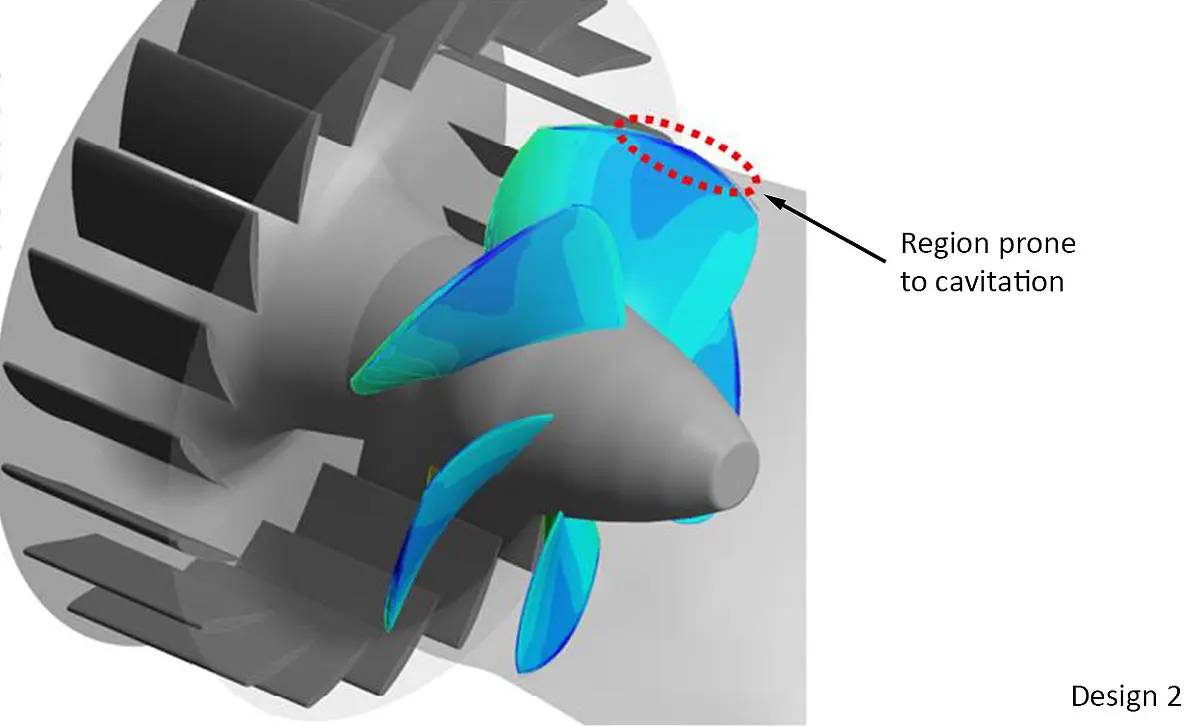
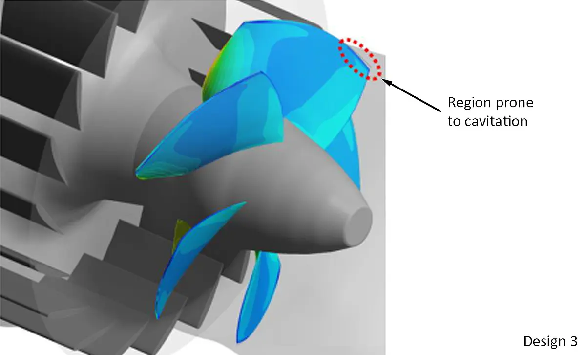
For the development of the new runner blade geometry, three different basic designs were analysed (see pictures below) in terms of their efficiency and cavitation behaviour. The designs were based on turbine designs we had created with similar rotational speed. The final design of the runner blade is ultimately the result of a series of tests and optimisations
During this, the effectiveness of anti-cavitation lips for Kaplan blades was also analysed. This showed that they did not improve cavitation behaviour in this specific case.
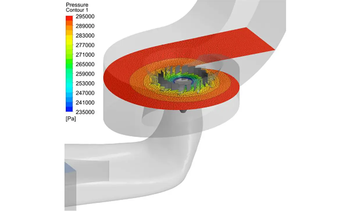
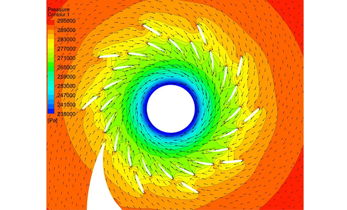
The simulation confirmed that the existing spiral casing is correctly designed for full load conditions and that the inflow conditions at the guide vanes are very good overall. In addition, the results showed that the combined losses in the spiral and guide vane area are at a comparatively low level, which further confirms the suitability of the spiral casing design.
For an operating point close to full load operation (H = 19.5 m, Q ≈ 68 m³/s), a visualisation of the flow in the spiral case and in the distributor was also created – see the following pictures.
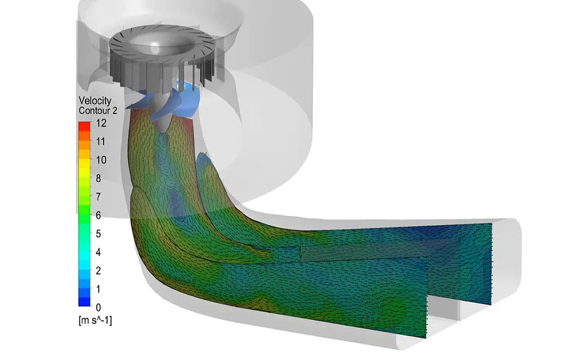
To analyse the flow in the draft tube, an overload operating point was analysed in more detail. Here, the visualisation clearly showed a largely homogeneous velocity distribution across various cross-sections and no areas with separated flow.
The results not only confirm the suitability of the draft tube design but also show that the new runner has been well adapted to the geometry of the existing draft tube.
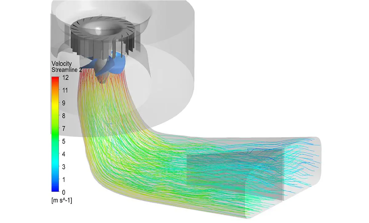
With the help of additional simulations at H=21.5 m and H=17.5 m, a turbine hill chart was created, which was also used to determine the ideal combination of guide vane and runner blade position. Ultimately, a peak efficiency of at least 94% was achieved.
Finally, a mesh sensitivity study was carried out at two operating points using the final runner geometry. This was done to check the influence of the mesh size on the simulation results. To this end, the mesh used for optimisation was sensitively refined and the total number of nodes was approximately doubled.

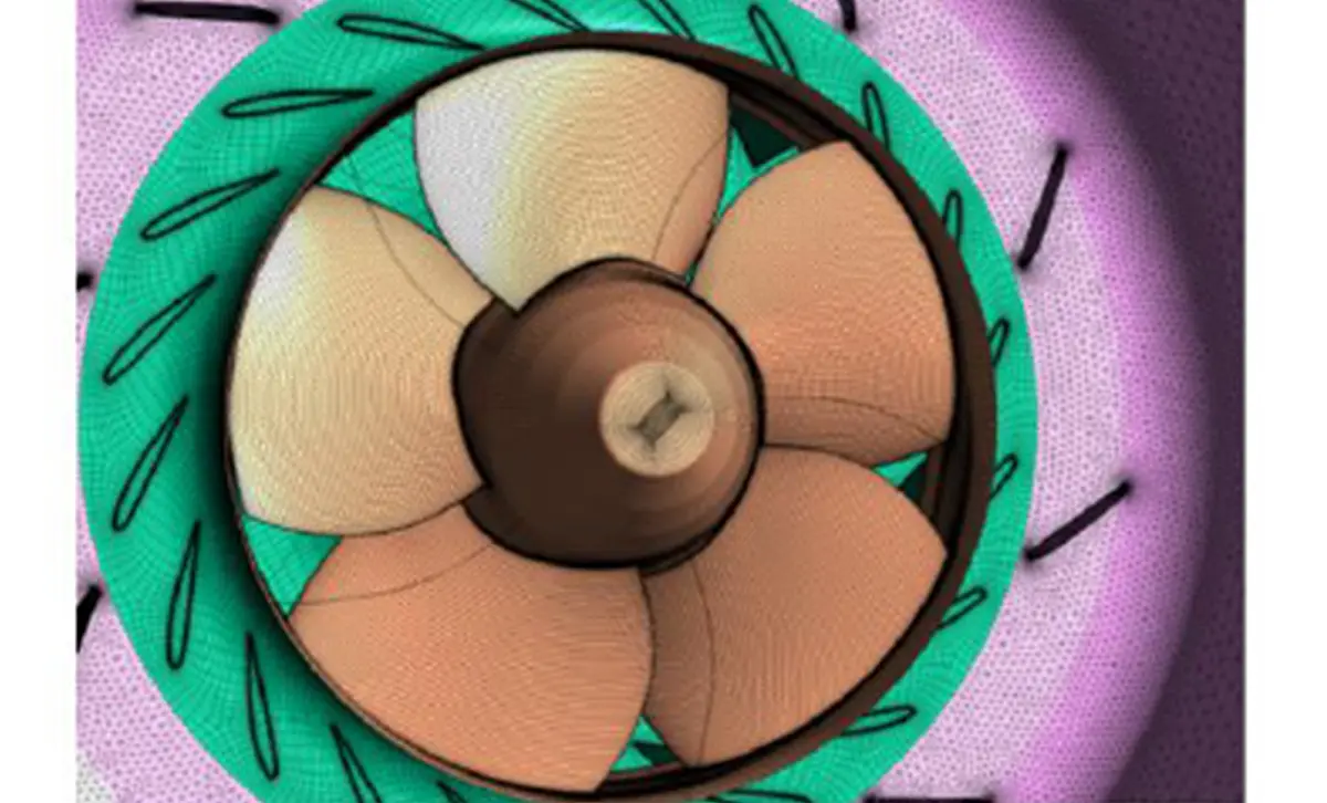
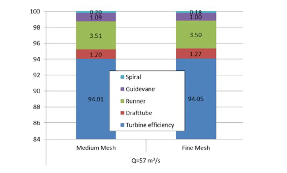
The study showed that this results in only a very small and negligible difference in efficiency and cavitation behaviour. The results can therefore be described as mesh-independent, which confirms our experience.
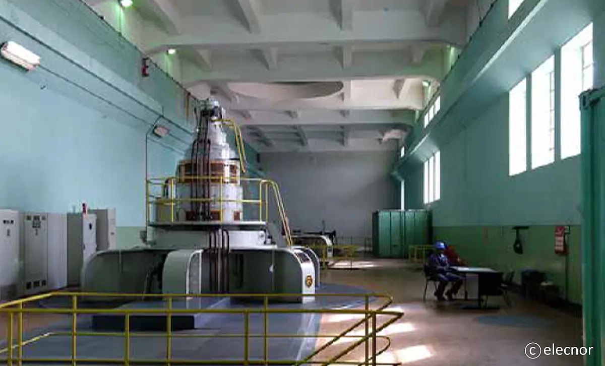
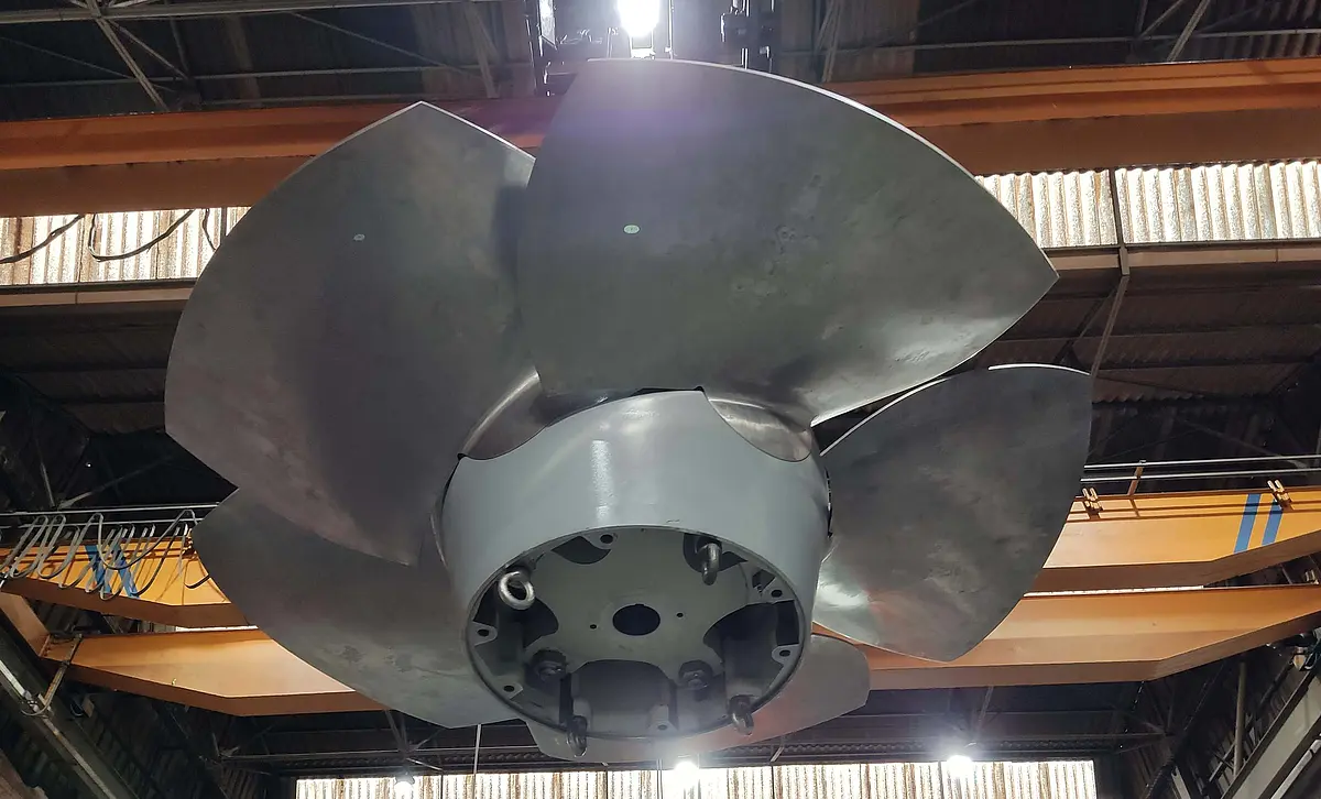
The turbines have now been operating successfully for several years, enabling a sustainable, stable electricity supply in the West African country.

Acoustic flow measurement

Our measuring methods

Subscribe to our newsletter and stay up to date on our activities, continuing education and conferences.
